Hall thrusters
Hall thrusters have a long history. They are discovered in the early 1960s in the U.S. and independently in the USSR but were abandoned in the West when it became apparent that there were strong instabilities which could not be completely eliminated. However, development continued in the USSR, particularly at the Kurchatov Institute in Moscow, under A.I. Morozov’s leadership. By the early 1980’s these engines had achieved operational status in the USSR, and have since flown in many (> 50) missions.
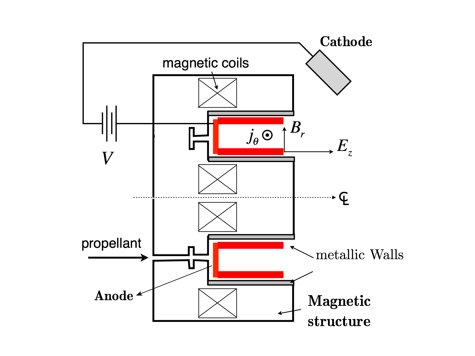
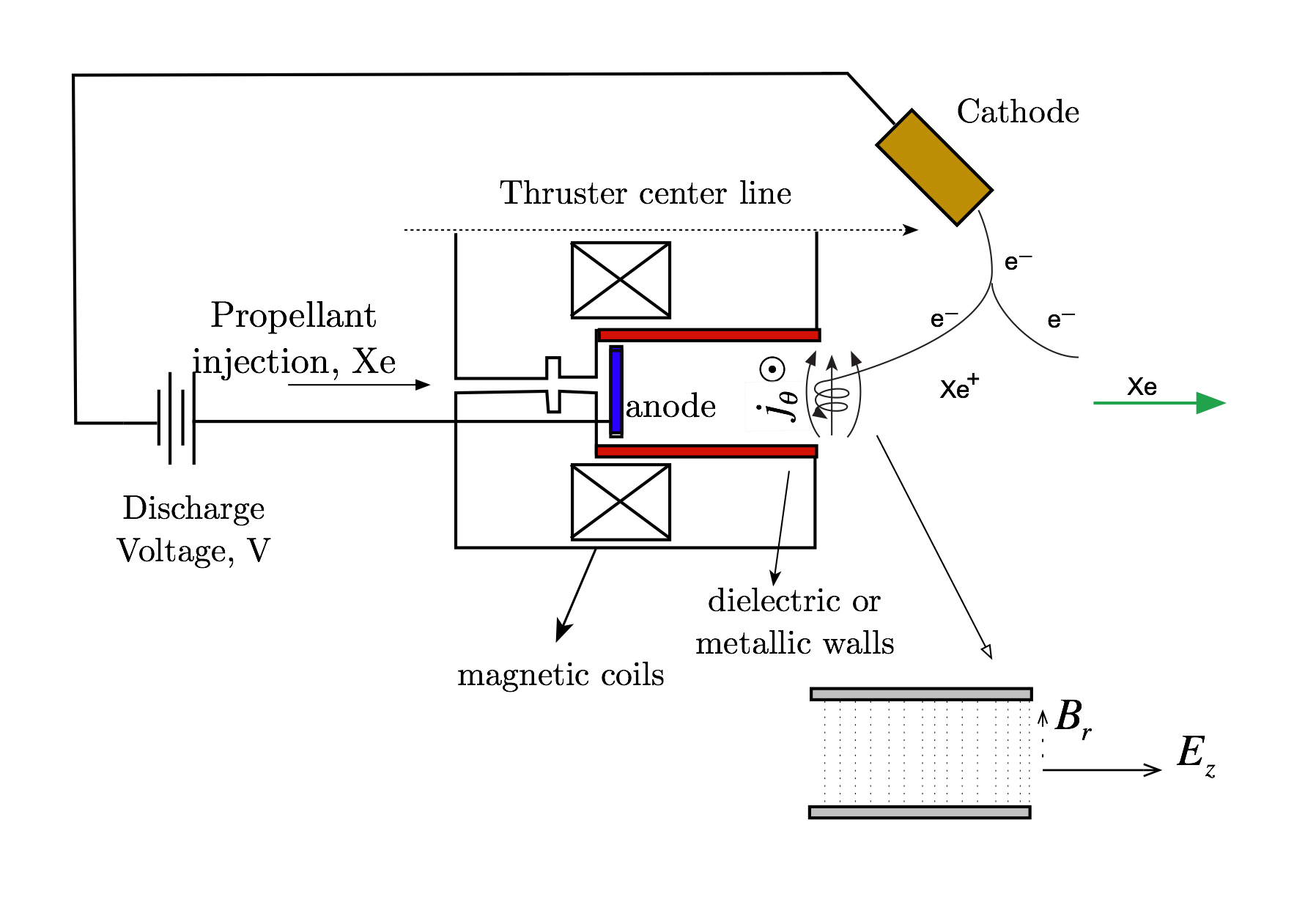
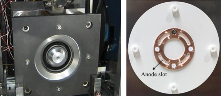
Many different varieties of Hall thrusters exist, created in several laboratories and companies around the world. Academic efforts have been directed mostly towards the understanding of ionization, electron trapping and diffusion, and loss mechanisms. In this laboratory the research is mainly concentrated on a particular variety called Thruster with Anode layer (TAL) in which the walls are at cathode potential and made of metal unlike the other variety called Stationary Plasma Thruster (SPT) in which the walls are made of insulated materials, such as Boron Nitride.
Anode layer type Hall thrusters have a metallic wall biased to the cathode potential to minimize the electron wall loss. Thus, the electron temperature inside the TAL type thruster is usually much higher than that of the SPT type and the necessary channel length is accordingly shorter.
Recent work has been directed towards the design and development of high-power anode layer Hall thrusters with particular emphasis on improving the efficiency and lifetime of the thruster.
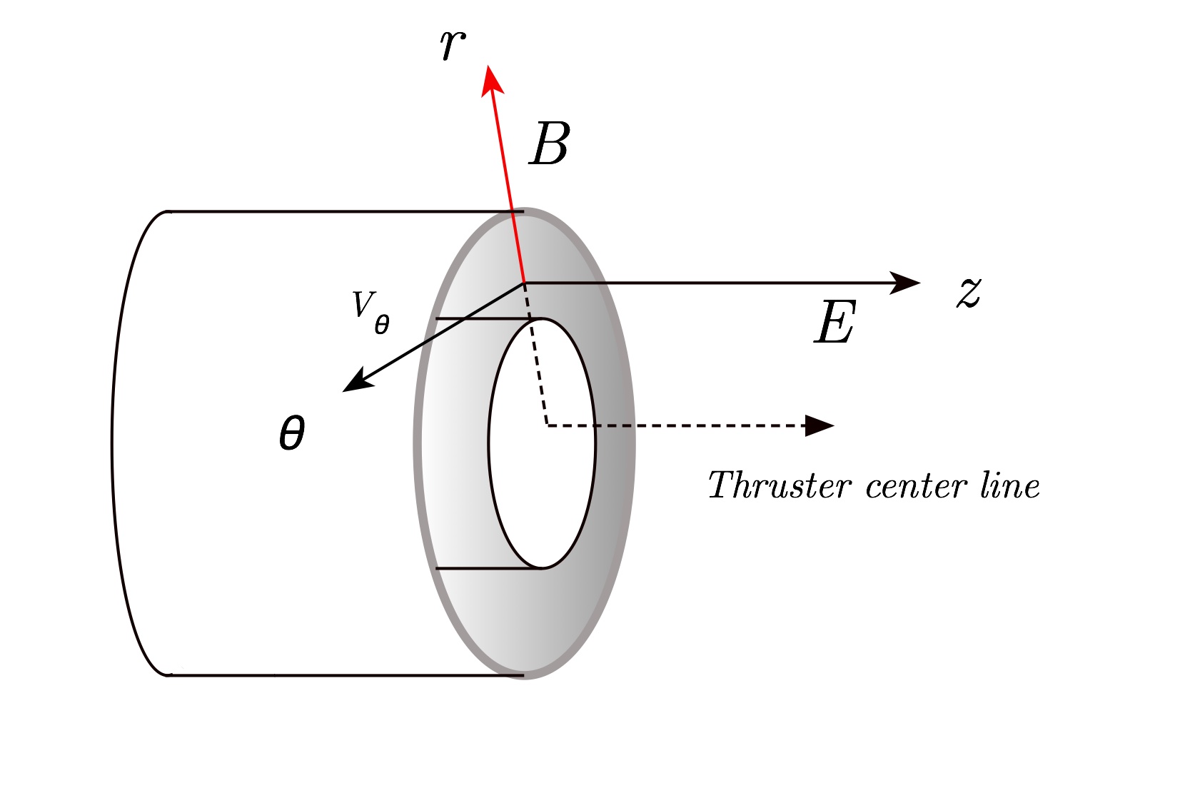
Hall thruster physics
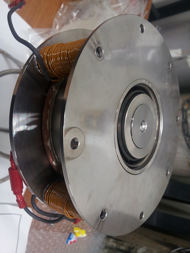
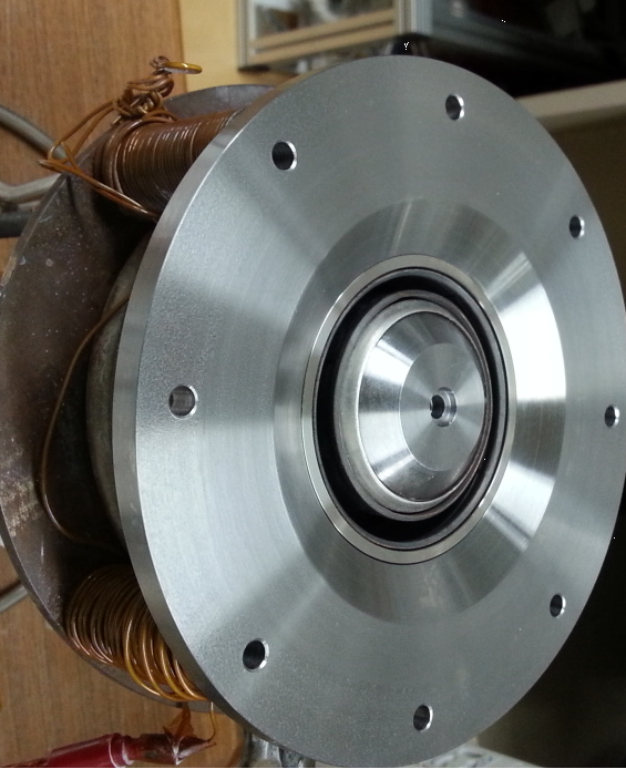
Some of the Hall thrusters developed in the laboratory
What is a Pulsed Plasma Thruster?
Pulsed Plasma Thruster, often referred to as PPT, are space propulsion systems that are applied on satellites.
Unlike chemical propulsion, the energy needed to produce the thrust comes from electric energy.
Due to their acceleration mechanism, PPT are categorized as electromagnetic accelerators, and are hence grouped together with,
for example, steady-state magnetoplasmadynamic (MPD) thrusters. Thus, PPT are sometimes also called Pulsed MPD Thruster.
Coaxial PPT mainly accelerate by electrothermal forces, and are, thus, also called Pulsed Electrothermal Thruster (PET).
Research and development of PPT started already in the 1950s and 60s, and resulted in the successful application of PPT onboard the Soviet satellite Zond-2 in 1964,
making them the first electric propulsion system in space! Since then research activities were continued worldwide and some more countries, including Japan,
have put a satellite with a PPT into space.
How does it work?
PPT consist mainly of 4 parts: a capacitor to store the energy, a pair of electrodes to establish the potential,
the propellant and the igniter. Depending on the design, PPT are further categorized.
Widely used is the nomenclature related to the state of matter of the used propellant:
♦ APPT (Ablative PPT) or SPPT (Solid Propellant PPT) in case of solid propellant, e.g., the widely used PTFE
♦ LPPT (Liquid Propellant PPT) in case of liquid propellant, e.g., water or methanol
♦ GPPT (Gaseous Propellant PPT) in case of gaseous propellant, e.g., argon or nitrogen
Either way, the propellant is fed in between the electrodes. In case of the isolating PTFE, it can be provided directly,
whereas liquid propellants mostly shortcut the system and need to be injected.
Before the operation, the capacitor is charged up to the working energy (typically some Joules).
The igniter is triggered and releases a spark containing electrons to close the electric circuit between the electrodes across the propellant.
The short-cut yields the main discharge of the oscillating circuit, and a discharge arc is formed.
The high current (of up to several kA) results in the ablation, dissociation and ionization of the propellant to a state of plasma.
Due to the high current, a strong magnetic field is formed that leads to a Lorentz force that pushes the particles out of the thruster and creates the thrust.
Due to the limited energy in the capacitor, the entire discharge time is about 10-20 ツオs, after which the arc collapses and the thrust production stops.
This is the pulsed operation, and the total thrust ability over the discharge time is called impulse bit.
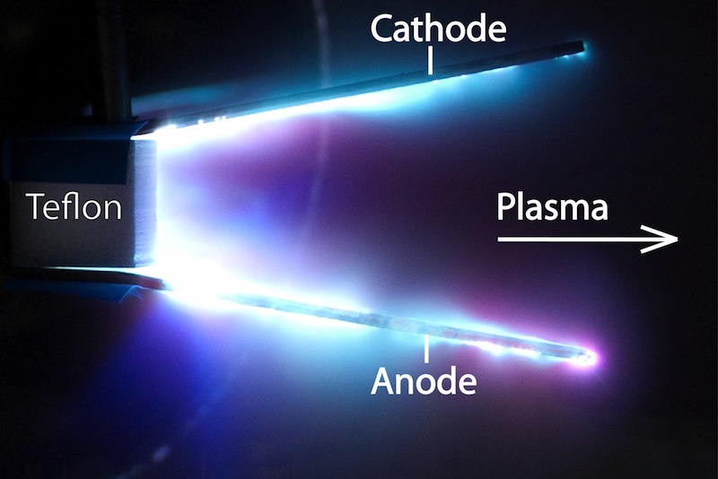
Pulsed Plasma Thruster during discharge
Current interests and further information
Our group studies on both SPPT and LPPT,
and we're focusing on the improvement of propellant utilization and the concept of advanced propellants for future application in space.
We further use plasma diagnostic methods to understand the physics of the discharge and the resulting plasma.
For more information, visit the research section and publications section.
Further, please also visit the website of the International PPT&iMPD Working Group of which we are a proud member.
Research Equipment
In Komurasaki laboratory, many probes are used for plasma investigation inside channel and plume.
♦Far-field Faraday Probe :
Far faraday probe consists of probe and rotating arm. Ion current distribution can be measured by sweeping probe in downstream of thruster. Ion beam current and plume divergence can be measured by using far faraday probe.
♦ Near-field Faraday Probe :
Hall thruster plume can’t be measured accurately by far faraday probe because thruster channel is annular. Near faraday probe can measure ion current distribution near channel and can measure plume shape more accurately than far faraday probe.
♦ Langmuir Probe :
Langmuir probe consists of single wire. Plasma density, plasma potential, electron current and floating potential can be measured by analyzing current when sweeping applied voltage.
♦ Emissive Probe :
Emissive probe is used for plasma potential measurement. Emissive probe is made of thoriated tungsten and inserted plasma with current heating. Plasma potential and floating potential is different in Langmuir probe measurement because of electron. But in Emissive probe measurement, plasma potential and floating potential is same because of thermal electron emitted from probe. Thus, Emissive probe can measure plasma potential more accurately than Langmuir probe.
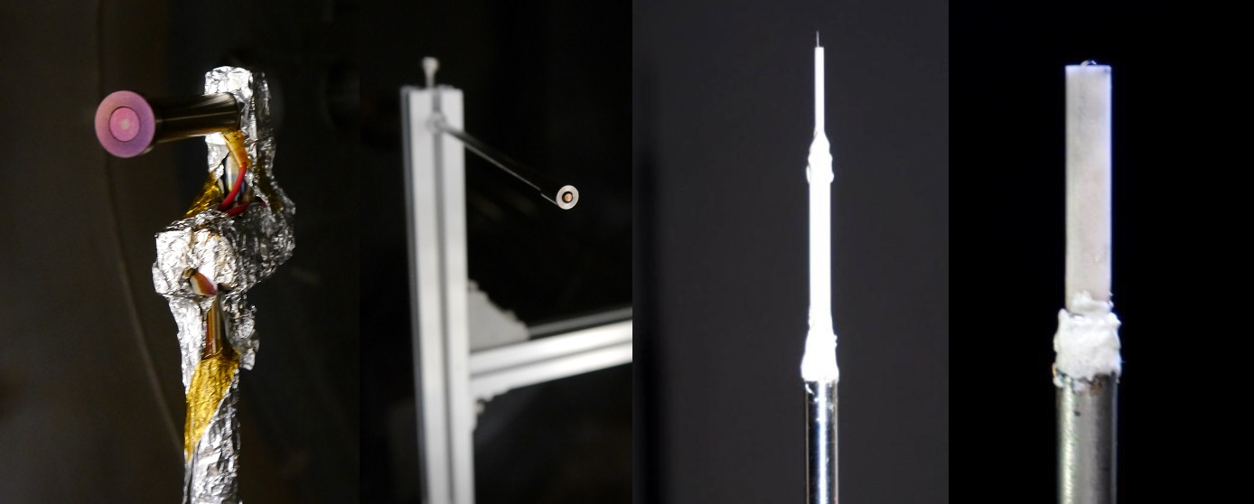
Far-field Faraday, near-field Faraday, Langmuir, and emissive probe
♦Thrust stand
Thrust stand is an equipment to measure thrust. Characteristics of the thruster is evaluated from thrust and discharge property. The accuracy of thrust measurement is necessary to know its characteristics precisely.
Our laboratory developed “Double pendulum type thrust stand”[1]. This stand is composed of inner and outer pendulum. Thruster is mounted on the inner pendulum, while a laser sensor is on the outer pendulum.
Advantages of this thrust stand are;
・Robustness on thermal drift: Canceling thermal input from discharge plasma between two pendulums. It results in eliminating thermal drift, a time-development error on thrust measurement.
・Real-time measurement: Small relaxation time of control supports to measure thrust at any time.
・Portability: Separated from the chamber system. This stand can be used in any vacuum chamber.
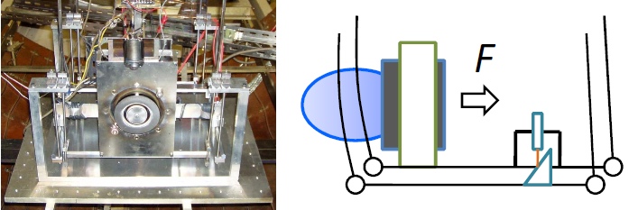
Dual pendulum type thrust stand (left). Thermal deformation by discharge plasma is cancelled between inner and outer pendulum. (right)
Current works
- Extension of measurement range
5 kW class Hall thruster (~200 mN) and several hundred W class Hall thruster (~20 mN) has been measured. The dual pendulum type thrust stand is applicable to thrusters with wide power range.
Examples of wide range thrusters. (Left)5 kW class RAIJIN94 (Right)500 W level XPT [2]
Past works
- Thermal drift cancellation
Dual pendulum type thrust stand can measure thrust without thermal drift. Whenever thermal deformation occurs on its pendulum, same amount of heat input is applied to both inner and outer pendulum. Its deformation is cancelled between two pendulums and thrust can be measured without thermal drift.
- Thrust vector measurement
2D thrust measurement is possible on this stand. Thrust vector control is important topic, which can replace gimbal and reduce weight of spacecraft. Accurate axial and radial thrust measurement helps to discuss the effectiveness of a thrust vector control design.
[1] Nagao, N., Yokota, S., Komurasaki, K., and Arakawa, Y., “Development of a two-dimensional dual pendulum thrust stand for Hall thrusters,” Review of Scientific Instruments, vol. 78, 2007, pp. 7-10.
[2] Karadag, B., Cho, S., Oshio, Y., Hamada, Y., Funaki, I. and Komurasaki, K., "Preliminaly Investigation of an External Discharge Plasma Thruster," AIAA Paper 2016-4951, 52nd AIAA/SAE/ASEE Joint Propulsion Conference, 2016.
Research Facilities
♦Vacuum chamber : Diameter 2 m x Length 3 m
Rotary Pump : ULVAC PKS-070, 7000 l/min × 2
Mechanical Booster Pump : ULVAC PMB-060B, 103300 l/min
Oil Diffusion Pump : ULVAC PFL-36, 37000 l/s
Cryopump : ULVAC CRYO-U20H, 10000 l/s (Ns)
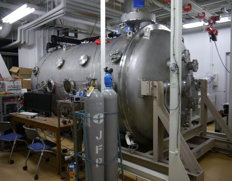 Vacuum chamber in basement of Eng. Bldg. 7.