HET Experiment
Anode layer type UT-58 thruster
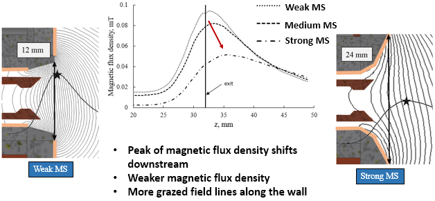
Magnetic shielding on Anode layer type:
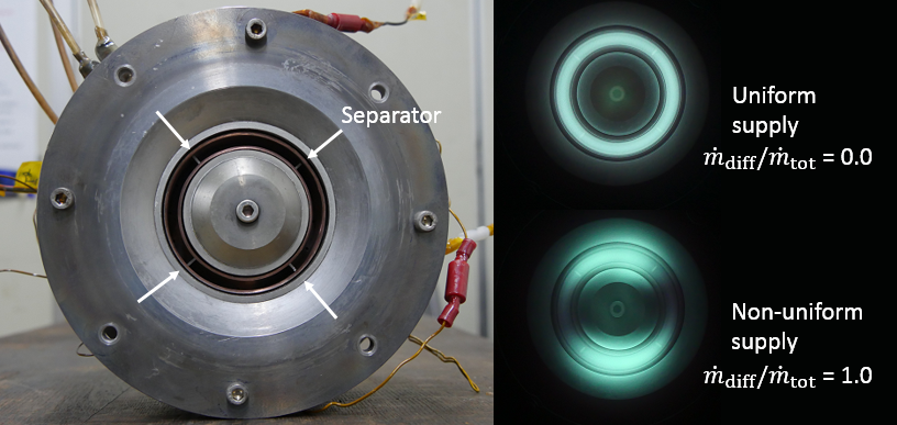
Suppression of discharge oscillation:
During past research [2], propellant was non-uniformly supplied in azimuthal direction, and the method was effective to suppress discharge oscillation, even though there was the expense of thrust efficiency due to increased electron current.
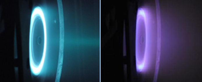
In this research, we are investigating azimuthal non-uniform plasma properties experimentally and numerically to reveal oscillation suppression mechanism, and to realize desirable technique to solve instability issue in Hall thrusters.
Alternative propellant:
- Bak, J., Hamada, Y., Hirano, Y., Komurasaki, K., Schonherr, T., and Koizumi, H., “Operational Properties of UT-58 Anode Layer Hall Thruster with Modified Magnetic Field and Guard-ring Material,” 52nd AIAA/SAE/ASEE Joint Propulsion Conference, 2016, pp. 1-10.
- Fukushima, Y., Yokota, S., Komurasaki, K., and Arakawa, Y., “Discharge Stabilization for an Anode-Layer-Type Hall Thruster by Azimuthally Nonuniform Propellant Supply,” Journal of the Japan Society for Aeronautical and Space Sciences, vol. 58, 2010, pp. 8-14.
- Fujita, D., Kawashima, R., Ito, Y., Akagi, S., Suzuki, J., Schonherr, T., Koizumi, H., and Komurasaki, K., “Operating parameters and oscillation characteristics of an anode-layer Hall thruster with argon propellant,” Vacuum, vol. 110, 2014, pp. 159-164.
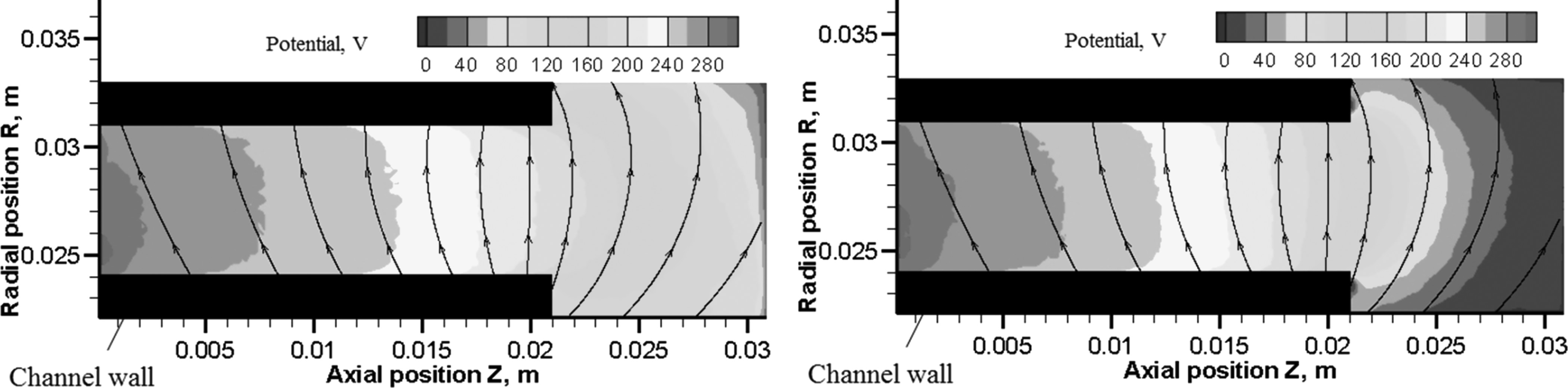
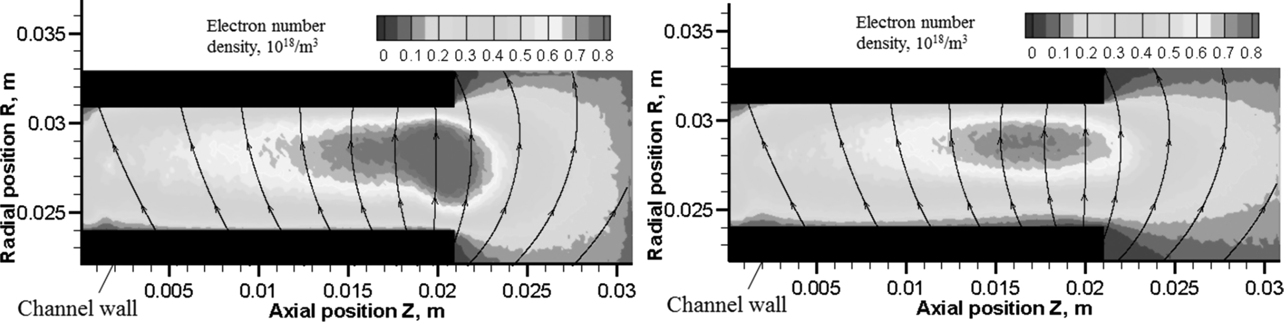
HET Simulation
In this laboratory the research is mainly focused on the fully kinetic and hybrid models.
Hybrid models
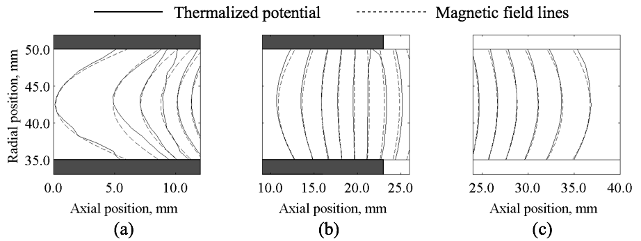
The hybrid PIC method using the HES approach is able to reproduce the fundamental characteristics of the Hall thruster discharge.
Electron fluid equations in HES approach
\begin{equation}
\frac{n_e}{\beta T_e}\frac{\partial \phi}{\partial \tau} + \nabla\cdot(n_e\,{\bf u}_e) = 0 \end{equation}
\begin{equation}
\left ( \begin{array}{ccc} b_x & \\
& b_y \end{array} \right )^{-1} \frac{\partial (u_{ez})}{\partial \tau} - [\mu] \nabla \phi = - u_e
\end{equation}
- R. Kawashima, K. Komurasaki, T. Schonherr, "A flux-splitting method for hyperbolic-equation system of magnetized electron fluids in quasi-neutral plasmas," Journal of Computational Physics, Vol. 310, pp. 202-212, 2016.
- R. Kawashima, K. Hara, K. Komurasaki, H. Koizumi, "A Unified Model for Axial-Radial and Axial-Azimuthal Hall Thruster Simulations," AIAA Propulsion and Energy, Salt Lake City, UT, July 25-27, 2016.
- R. Kawashima, K. Komurasaki, T. Schonherr, "A hyperbolic-equation system approach for magnetized electron fluids in quasi-neutral plasmas," Journal of Computational Physics, Vol. 284, pp. 59-69, 2015.
- R. Kawashima, T. Schonherr, K. Komurasaki, "Modeling of Electron Fluids in Hall Thrusters Using a Hyperbolic System," AIAA Propulsion and Energy, Cleveland, OH, July 28-30, 2014.
Kinetic models
- S. Cho, K. Komurasaki, Y. Arakawa, "Kinetic particle simulation of discharge and wall erosion of a Hall thruster," Physics of Plasmas, 20, 063501, 2013
PPT Experiment
What are difficulties of Solid Propellant PPT?
Although PPT is expected to applied to microsatellites due to its simplicity and compactness, there are some difficulties in Solid Propellant PPT.
Following difficulties are concerned for PPT using solid propellant (PTFE) for its propellant.
1. Excessive propellant supply from the PTFE surface after the main discharge (late time ablation).
2. Uneven propellant consumption on the PTFE surface (uneven propellant consumption).
3. Contamination of other parts of the satellite by carbon or fluorine in the exhaust gas (contamination).
Problem 1 is considered to be one of the main reasons degrading the thrust efficiency of PPT. Propellant supplied after the main discharge are not accelerated to high velocity because they do not experience the electric acceleration sufficiently.
Problem 2 is caused by the passive propellant supply function of solid propellant PPT. Uneven propellant surface can decay the thruster performance in long-term missions.
Problem 3 doesn't affect the thrust efficiency, but this problem can be crucial for real applications. Black carbon and chemically reactive fluorine can cause unexpected effects on other parts, or other satellites in constellation missions.
Liquid Propellant PPT
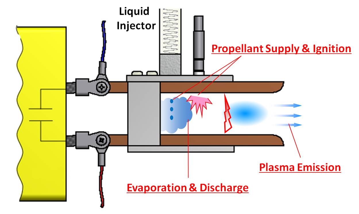
Liquid Propellant Pulsed Plasma Thruster
The big difference between solid propellant PPT and LPPT is propellant supply function. LPPT pour an optimal amount of liquid between the electrodes, and fire the igniter with slight delay from injector.
Accorgin to this active propellant supply function, LPPT has solutions for the difficulties mentioned above.
1. Due to its active propellant supply, LPPT avoid the problem of excessive propellant supply by late time ablation.
2. The probem of uneven propellant supply can be solved as well.
3. Water doesn't affect other parts of the satellites.
As described above, LPPT can solve the crucial problems of solid propellant PPT. However, there are also some difficulties in LPPT like management of liquid in vacuum condition, design of an injector with a good responce, and evaporation of water for ionization. We are trying to find solutions for these problems of LPPT.
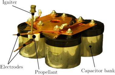
Develpment of High Performance PPT for Lunar Mission BW-1
Researches of a high performance solid propellant PPT (ADD SIMP-LEX) are conducted in Kashiwa PPT team for the application of ADD SIMP-LEX to the main thruster system of Lunar Mission BW-1.
This thruster has been developed in IRS (Institute of Space Systems), and plasma diagnostics and elucidation of physics in PPT are mainly conducted in out laboratory.
This thruster is optimized in terms of discharge circuit parameters and electrode shape in experimental method, and achieved the specific impulse of about 2700s, which is relatively high for its energy level.
The characteristics of this thruster are flared triangular electrodes, multiple bank capacitors, and side-fed configration.
Our group welcomes international students. We daily have active discussions on researches in English, while the international students train their Japanese skill.
If you are thinking about the research experience in our laboratoty, please contact us!
 |
 |
| ADD SIMP-LEX | Lunar Mission BW-1 |
Mantis-a templates, visit Netmeter